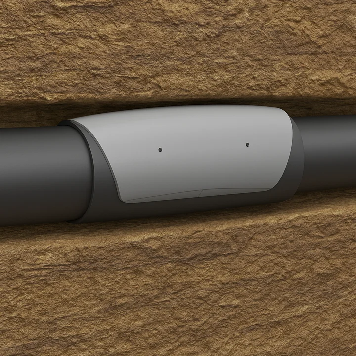
3D render of a CE-BOND annular flow diverter mounted on casing inside the openhole formation
CE-BOND · Annular flow diverter

Improve cement placement in eccentric, deviated wellbores.

CE-BOND is a self-orienting annular flow diverter designed to reduce circumferential velocity imbalance around casing and support improved low-side displacement during primary cementing.

CE-BOND annular flow diverter on casing · 3D render
> 15°Designed to orient by buoyancy in deviated wellbores
Job-specificSpacing and placement based on casing size, hole size, inclination and cementing objectives
With centralizersSupplements conventional centralization — it does not replace it
No rig time impactInstalled during casing preparation, with no mechanical setting sequence required while running in hole
Bond log evidenceField evaluation shows low-side channel termination at the CE-BOND interval
The problem

Centralizers improve standoff, but residual low-side displacement risk can remain.

In deviated wellbores, casing often sits eccentrically despite centralization. Displacement fluids preferentially flow through the wider high side of the annulus, while the restricted low side can remain poorly swept. This can leave mud, solids or contaminated fluid behind the casing and increase the risk of a low-side cement channel.

Deviated openhole · eccentric casing
Diagram of eccentric casing in a deviated openhole with numbered markers: 1 high-side preferential flow above the pipe, 2 path of least resistance, 3 mud and solids retained on the restricted low side
Uneven flow distribution around the pipe driven by eccentricity — the centralizer improves standoff but may not fully correct the velocity imbalance
  • 01
    Eccentric annulus

    Even with centralizers, the casing may remain offset from the hole centreline. This creates a wide high-side flow path and a restricted low-side annular gap.

  • 02
    Preferential high-side flow

    During displacement, fluids naturally follow the path of least resistance. The high side receives most of the flow, while the low side sees reduced velocity.

  • 03
    Low-side channel risk

    If mud, solids or contaminated fluid remain on the low side, cement may not fully replace the displaced fluid, increasing the risk of a continuous channel behind casing.

How CE-BOND works

Redistribute annular flow where eccentricity creates the largest imbalance.

A series of CE-BOND diverters creates local flow redistribution around the casing. In eccentric annuli, displacement flow naturally favors the wider high side. CE-BOND introduces a controlled diversion effect, forcing part of the flow toward the restricted low side. When run in series with conventional centralizers, this increases low-side velocity and improves the probability of effective mud removal before cement placement.

Mechanism · CE-BOND flow diverters in series
CE-BOND flow diverters in series on casing redirecting annular flow toward the low side to improve circumferential cement placement
Original CE-BOND drawing showing flow diverters installed in series on the casing to improve low-side displacement and circumferential cement placement.
01

Flow redistribution

CE-BOND redirects part of the annular flow from the high side toward the low side of the eccentric annulus.

02

Improved low-side sweep

The diverted flow helps mobilize mud, solids and contaminated fluid that can otherwise remain on the low side before cement placement.

03

Improved conditions for circumferential cement placement

Improved low-side displacement supports better circumferential cement coverage and reduces the likelihood of a continuous channel behind casing.

Positioning

CE-BOND is not a centralizer replacement. It is an annular flow diverter, run with conventional centralizers.

Centralizers improve standoff. CE-BOND addresses the remaining flow distribution problem — the poor low-side displacement regime that standoff alone does not always correct. Good standoff design remains a requirement of every program.

Orientation

Buoyancy-oriented to place the diversion effect on the high side.

CE-BOND uses buoyant elements — syntactic foam rated for downhole pressure — to orient the diverter toward the high side of the casing in deviated wellbores. This positions the flow diversion geometry so that annular flow is redirected toward the low side of the hole. Orientation should be reviewed against well inclination, casing rotation risk, centralizer program and job-specific running conditions.

Orientation testing

Self orientation demonstrated physically.

The self-orientation mechanism requires no downhole activation.

Design principle

Buoyancy helps orient CE-BOND toward the high side of the annulus.

CE-BOND uses buoyant material and asymmetric geometry to orient the tool toward the high side in deviated wellbores. The geometry increases resistance in the preferential high-side flow path, encouraging redistribution toward the low side. Application suitability is reviewed against inclination, geometry, fluid properties and operational constraints.

Self orienting No activation Used with centralizers
Validation

Physical testing and flow modelling support the same redistribution mechanism.

CE-BOND has been evaluated using physical flow-loop testing and annular-flow modelling. The two methods serve different purposes: the flow loop demonstrates displacement behaviour, while modelling supports mechanism understanding and application design.

Physical flow-loop testing

Observe the displacement behaviour directly.

The test video demonstrates the effect of CE-BOND on low-side cuttings and debris removal under the tested geometry and flow conditions.

Annular velocity distributionCFD comparison
CFD velocity comparison with and without CE-BOND
Same colour scale. The comparison illustrates redistribution of the circumferential velocity field. CFD is design support and mechanism evidence, not a downhole velocity measurement.
The engineering objective is not to create the highest possible local velocity. It is to reduce the circumferential velocity imbalance that can leave the restricted low side poorly displaced.
Field evidence

Field cement evaluation provides evidence of improved circumferential response across selected CE-BOND intervals.

Bond log interpretation in the field example below shows a low-side channel below the CE-BOND interval. The channel terminates at the deepest CE-BOND location, with improved circumferential cement response above the tool interval. This is an observed cement-evaluation outcome and should be interpreted together with the full log, well geometry, centralization programme and cement-job record.

Impedance Z map · composite cement map
Annotated cement bond log: a low-side channel path is visible below the CE-BOND interval in both the impedance Z map and composite cement map; the channel terminates at the deepest CE-BOND tool, with improved circumferential cement response above the tool interval
Field cement evaluation showing low-side channel response below the CE-BOND interval and channel termination at the deepest CE-BOND tool. Interpretation should be reviewed together with the full cement evaluation log, well geometry, centralization program and cement job record.

The observed low-side channel terminates at the deepest CE-BOND tool in this field example.

A low-side channel is visible below the CE-BOND interval in both the impedance and composite cement maps. The channel terminates at the deepest CE-BOND tool. Above the CE-BOND interval, the cement map shows improved circumferential response, consistent with improved low-side displacement.

The improved bond response above the tool interval is consistent with improved low-side displacement and reduced retention of mud, solids or contaminated fluid. Interpretation should be considered together with the complete cement evaluation, well geometry and cement-job record.

  • Observed channel response

    In the field example shown, the low-side channel visible below the equipped interval terminates at the deepest CE-BOND location.

  • Comparison where available

    The detailed field case histories include same-well and same-job comparisons, together with depth-matched cement evaluation where available.

  • Evaluation context matters

    Cement response reflects the complete placement system, including centralization, conditioning, fluids and execution. CE-BOND is evaluated as one component of that system.

  • Centralization still matters

    Good casing centralization remains important when CE-BOND annular flow diverters are used. CE-BOND supplements the standoff programme, it does not replace it.

Field experience

Access selected CE-BOND field case histories.

These technical case histories provide examples of CE-BOND field applications across different casing sizes, well geometries and operating environments, including running performance and post-job cement evaluation.

Technical case histories

Review the detailed field evidence.

Register your name, company and work email, then immediately open or download the selected CE-BOND technical case histories. Your details are used only to provide the requested material and respond to related technical enquiries.

Access case histories
Design inputs

Typical information reviewed for a CE-BOND application.

Not every item is required for an initial assessment. The review is tailored to the available well data and the specific cement placement challenge.

CE-BOND composite construction cutaway
Application engineering

Designed against the actual casing, hole and cementing envelope.

Tool geometry, clearance, placement, spacing and hydraulic effect are reviewed for the specific application. Centralization, pump rate, fluid properties, running constraints and the interval at risk remain part of the overall cementing design.

01Casing size and hole geometry
02Inclination across the target interval
03Centralizer type, spacing and expected standoff
04Mud, spacer and cement program
05Pump rate and displacement schedule
06Available cement evaluation or offset well data
Installation

Installed during casing preparation, with no downhole activation step.

CE-BOND slips over the casing body and is retained axially between two stop collars. Installation can be completed offline in the pipe yard before the casing or liner is mobilized to the rig.

Example installation arrangementCE-BOND + centralizers
CE-BOND installation schematic showing the tool retained between stop collars and positioned relative to casing centralizers
Example configuration only. Final placement and spacing are set for the specific well application.
Operational integration

Run as part of the casing or liner string.

The tool has no powered, hydraulic or mechanically actuated components and requires no downhole activation. Clearance, runability and hydraulic effects are checked during the application review.

Slip-on 2 stop collars Offline preparation
CE-BOND on casing · field and yard photos
CE-BOND annular flow diverter installed on casing
CE-BOND annular flow diverter on casing during preparation
CE-BOND annular flow diverter fitted on casing with stop collars
Applications

Applications where low-side displacement matters.

CE-BOND is applied where eccentricity and low-side displacement are recognized risks to cement placement and isolation.

Primary cementing in deviated wells

Support low-side displacement

Improves low-side sweep in eccentric annuli where conventional displacement may leave mud or contaminated fluid behind casing.

Highly inclined & horizontal sections

Target the channel-prone intervals

Targets intervals where gravity, eccentricity and low-side solids retention increase channel risk.

P&A barrier cementing

Support challenging barrier cement placement

Potential application where annular cement placement is important to a planned barrier, subject to the operator’s barrier design and acceptance criteria.

Known poor-bond intervals

Target recurring displacement risk

Applicable where offset wells or previous cement evaluation logs show recurring low-side channeling.

Casing & liner cementing

Run as part of the string

Designed for casing or liner deployment, subject to job-specific clearance, runability and hydraulic review.

Operator value

The value is an additional hydraulic control for difficult cement placement.

CE-BOND is intended to address residual circumferential velocity imbalance in deviated, eccentric annuli. Its value is strongest where conventional centralization and displacement design still leave a recognized low-side placement risk.

01 Reduced high-side flow dominance
02 Improved low-side displacement conditions
03 More uniform circumferential flow distribution
04 Self orienting integration with casing or liner
05 Application-specific placement and spacing
06 Field evidence supported by cement evaluation
Centraflow Engineering

Specialist cement placement engineering, beyond the product.

Centraflow also supports operators with focused engineering around cement placement, cement evaluation, annular flow modelling, centralization, casing movement and technical assurance. The engineering starts with the well challenge, not with a predetermined technology.

  • 01
    Cement placement engineering

    Review geometry, standoff, fluid hierarchy, rates and displacement risk.

  • 02
    Cement evaluation

    Interpret acoustic and ultrasonic response and translate findings into placement lessons.

  • 03
    Annular flow modelling

    Assess eccentric annulus hydraulics and circumferential velocity distribution.

  • 04
    Technical assurance

    Independent review of cementing and barrier programmes before execution.

Work with Centraflow

Contact Centraflow

Contact us for CE-BOND application support, technical discussions, partnerships or general enquiries. For a specific well or project, provide the available application details below.

Centraflow · Energivegen 10, 4056 Tananger, Norway
centraflow.no

Your enquiry is sent directly to Centraflow. The receiving email address is not exposed on the website.

CE-BOND · Annular flow redistribution for challenging cement placement